Share

Thursday, September 30, 2010

How to Repair Electronic Steering

How to Repair Electronic Steering

This can aply to all brand of Automobile that consist of EPS (Electronic Power Steering)


Hyundai I30 Steering System


AUTO REPAIR AND STUDY GUIDE AND DESCRIPTION

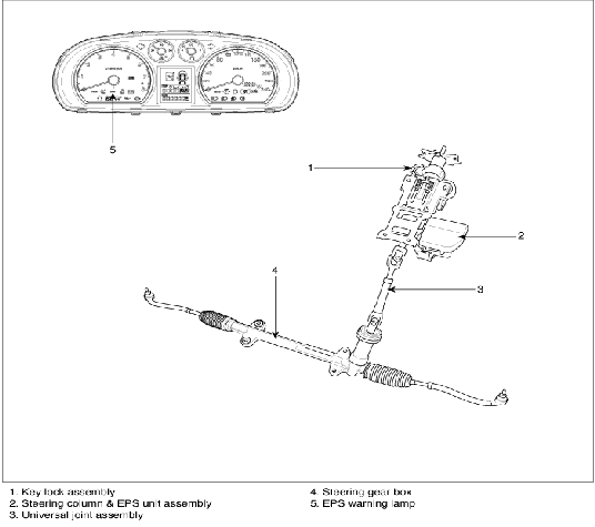
Study Guide of EPS (Electric power steering, Column assist type) system uses an electric motor to assist the steering force and it is an engine operation independent steering system.

Study Guide of EPS control module controls the motor operation according to information received from the each sensor and CAN (Controller Area Network), resulting in a more precise and timely control of steering assist than conventional engine-driven hydraulic systems.

Components (Steering Angle Sensor, Torque Sensor, Fail-safe relay, etc.) of the EPS system are located inside the steering column & EPS unit assembly and the steering column & EPS unit assembly must not be disassemble to inspect or replace them.

NOTES WITH REGARD TO DIAGNOSIS

Trouble factor

Check item

Trouble symtom

Explanation

Note

Drop, impact, and overload

Motor

Abnormal noise

-

Visable or unvisable damage can occur.

The steering wheel could pull to one side by using the dropped parts.

-

Precise parts of motor/ECU are sensitive to vibration and impact.

-

Overload can cause unexpected damage

-

Do not use the impacted EPS.

-

Do not overload each parts.

ECU

Circuit damage

-

Wrong welding point

-

Broken PCB

-

Damaged precise parts

Torque sensor

Insufficient steering effort

Overload to INPUT shaft can cause malfunction of the torque sensor

-

Do not impact the connecting parts (When inserting and torquing)

-

Use the specified tool to remove the steering wheel. (Do not hammer on it)

-

Do not use the impacted EPS

Shaft

Insufficient steering effort (Uneven between LH and RH)

Do not use the impacted EPS

Pull/Dent

Harness

-

Malfunction-impossible power operation

-

Malfunction of EPS

Disconnection between harness connecting portion and harness

Do not overload the harness

Abnormal storage temperature

Motor/ECU

Abnormal steering effort by improper operation of the motor/ECU

-

Waterproof at the normal condition

-

Even a little moisture can cause malfunction of the precise parts of the motor/ECU

-

Keep the normal temperature and proper moisture, while storaging

-

Avoid drowning

1.

Do not impact the electronic parts, if they are dropped or impacted, replace them with new ones.

2.

Avoid heat and moisture to the electronic parts.

3.

Do not contact the connect terminal to avoid deformation and static electricity.

4.

Do not impact the motor and torque sensor parts, if they are dropped or impacted, replace them with new ones.

5.

The connector should be disconnected or connected with IG OFF.


COMPONENTS

clip_image003

Auto Repair and Study Guide , Auto Repair and Study Guide


GENERAL INSPECTION

After or before servicing the EPS system, perform the troubleshooting and test procedure as follows. Compare the system condition with normal condition in the table below and if abnormal symptom is detected, perform necessary remedy and inspection.

Test condition

Normal condition: Motor must not supply steering assist.

Symptom

Possible cause

Remedy

IG Off

Motor supplies steering assist.

ASP is not calibrated.

Perform the ASP calibration using a scan tool.

IG power supplies

Inspect the IG power supply line.

Test condition

Normal condition: Motor must not supply steering assist, Warning lamp is illuminated.

Symptom

Possible cause

Remedy

IG On/Engine Off

Motor supplies steering assist.

ASP is not calibrated.

Perform the ASP calibration using a scan tool.

EMS CAN signal is not received.

Inspect the CAN line.

Warning lamp is not illuminated.

Cluster fault

Inspect the cluster and cluster harness

Test condition

Normal condition: Motor supplies steering assist, Warning lamp is not illuminated.

Symptom

Possible cause

Remedy

IG On/Engine On

Warning lamp is illuminated and Motor dose not supply steering assist.

EPS (Hot at all times) and IG power supply fault

Inspect the connector and harness for EPS (Hot at all times) and IG power supply line.

DTC is detected by system.

Perform the self test using a scan tool and repair or replace.

Warning lamp is illuminated and Motor supplies steering assist.

ASP is not calibrated.

Perform the ASP calibration using a scan tool.

CAN communication between EPS and cluster is fault.

Inspect the CAN line.

ASP: Absolute Steering Position

CAN: Controller Area Network

EMS: Engine Management System

clip_image004

Auto Repair and Study Guide

The following symptoms may be occurred during normal vehicle operation and if there is no EPS warning light illumination, it is not malfunction of EPS system.

After turning the ignition switch on, the steering wheel becomes heavier while it performs EPS system diagnostics, for about 2 seconds, then it becomes normal steering condition.

After turning the ignition switch on or off, EPS relay noise may occur but it is normal.

When it is steered, while the vehicle is stopped or in low driving speed, motor noise may occur but it is normal operating one.

Caution when ASP (Absolute Steering Position) calibration or EPS type recognition

Check if the battery is fully charged before ASP calibration or EPS type recognition.

Be careful not to disconnect any cables connected to the vehicle or scan tool during ASP calibration or EPS type recognition.

When the ASP calibration or EPS type recognition is completed, turn the ignition switch off and wait for several seconds, then start the engine to confirm normal operation of the vehicle.

Scan tool (Hi-Scan Pro) installation

1.

Attach the CAN interface module to the Hi-Scan Pro main body and securely tighten the two bolts.

2.

Install the CAN interface module to the Data Link Cable and securely tighten the two bolts.

ASP calibration procedure

1.

Plug DLC cable from a scan tool into the vehicle's data link connector located under the instrument panel on the driver's side.

2.

Turn the ignition switch ON position.

3.

Turn the steering wheel so that the front wheel can face straight ahead.

4.

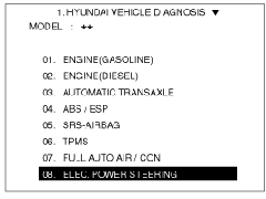
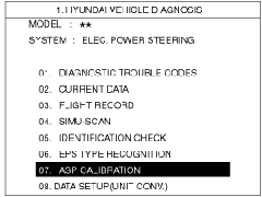
Select a model and ELECTRIC POWER STEERING.

clip_image005

5.

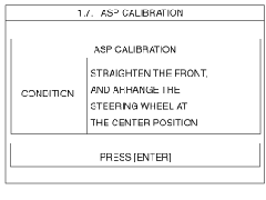
Select the ASP CALIBRATION and press ENTER.

clip_image006

6.

Check the massage on the screen and press ENTER'.

clip_image007

7.

Confirm the vehicle condition (IG On) and then turn the steering wheel until massage changes to the next screen.

clip_image008

8.

When the massage is displayed on the screen as follows, turn the steering wheel so that the front wheel can face straight ahead and then press ENTER.

clip_image009

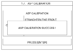
9.

When the calibration is completed, the massage will be displayed on the screen as follows.

clip_image010

EPS type recognition procedure

1.

Plug DLC cable from a scan tool into the vehicle's data link connector located under the instrument panel on the driver's side.

2.

Turn the ignition switch ON position.

3.

Select a model and ELECTRIC POWER STEERING.

clip_image005[1]

4.

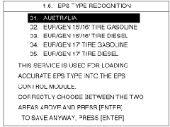
Select the EPS type recognition and press ENTER.

clip_image011

5.

Select the affected area and press ENTER.

clip_image012

6.

When the EPS type recognition is completed, the massage will be displayed on the screen as follows.

clip_image013

more information and Study Guide

Wednesday, September 29, 2010

How to Replace Spark Plug of Azera

How to Replace Spark plug of Azera

Model: Hyundai Azera (TG),ViraCruz , Genesis BH , Sonata

Year Model: 2010

Fuel : Gasoline

Displacement:3300 cc and 3800cc


2009  G 3.3 DOHC  Engine Electrical System


Auto Repair and Study Guide  to Removal

IGNITION COIL

1.

Remove the engine cover.

2.

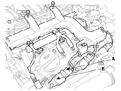
Disconnect the ignition coil connector(A).

clip_image002

Auto Repair Notice


When removing the ignition coil connector, pull the lock pin(A) and push the clip(B).

clip_image004

3.

Remove the ignition coil (B).

4.

Installation is the reverse of removal.

ON-VEHICLE INSPECTION

SPARK TEST

1.

Remove the ignition coil connector(A).

clip_image002[1]

Auto Repair and Study Guide to Notice


When removing the ignition coil connector, pull the lock pin (A) and push the clip(B).

clip_image004[1]

2.

Remove the ignition coil(B).

3.

Using a spark plug socket, remove the spark plug.

4.

Install the spark plug to the ignition coil.

5.

Ground the spark plug to the engine.

clip_image005

6.

Check if spark occurs while engine is being cranked.

Notice for Auto Repair and Study Guide


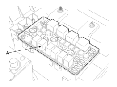
To prevent fuel being injected from injectors while the engine is being cranked, remove the fuel pump relay(A) from the fuse box.

Crank the engine for no more than 5 ~ 10 seconds.

clip_image006

7.

Inspect all the spark plugs.

8.

Using a spark plug socket, install the spark plug.

9.

Install the ignition coil.

10.

Reconnect the ignition coil connector.

clip_image007

Study Guide to INSPECT SPARK PLUG

1.

Remove the ignition coil connector(A).

clip_image002[2]

Notice for Auto Repair and Study Guide


When removing the ignition coil connector, pull the lock pin(A) and push the clip(B).

clip_image004[2]

2.

Remove the ignition coil(B).

3.

Using a spark plug socket, remove the spark plug.

Study Guide and Caution


Be careful that no contaminates enter through the spark plug holes.

4.

Inspect the electrodes (A) and ceramic insulator (B).

clip_image009

Auto Repair and Study Guide to INSPECTION OF ELECTRODES

Condition

Dark deposits

White deposits

Description

-

Fuel mixture too rich

-

Low air intake

-

Fuel mixture too lean

-

Advanced ignition timing

-

Insufficient plug tightening torque

5.

Check the electrode gap (A).


Standard :

Unleaded : 1.0 ~ 1.1 mm (0.0394 ~ 0.0433 in.)


clip_image010

INSPECT IGNITION COIL

1.

Measure the primary coil resistance between terminals (+) and (-).

clip_image011


Standard value: 0.62Ω ± 10%


Study Guide , Study Guide , Study Guide , Study Guide , Study Guide , Study Guide ,

For more study  and Guide

Tuesday, September 28, 2010

How to Know The Cause of Code U0101

How to Know the Cause of Code U0101 Of Hyundai

This Trouble Shooting Code may Help You much to easily distinguish the real problem.

Model: Hyundai Elantra (HD)

Year Model:2010

Fuel: Gasoline

Displacement: 1600cc 


U0101 ECM-TCM CAN Error


Study Guide and Component Location

clip_image004

Study Guide and DTC Description

If there is no message from TCU to ECM through external CAN line over 500 ms, PCU sets DTC U0101.

Auto Repair and DTC Detecting Condition

Item

Study Guide and Detecting Condition

Study Guide and Possible Cause

DTC Strategy

● CAN communication status check

● Poor connection
● PCM

Enable Conditions

● TCU is not coming via internal CAN

Threshold Value

● No message time from TCU via external CAN 500ms

Diagnostic Time

● Continuous

MIL ON Condition

● 5 sec

Study Guide , Study Guide , Study Guide , Study Guide , Study Guide , Study Guide

More and more 

How to Check The Shock Shifting of Hyundai=Poor Contact

How to Check the Shock Shifting of Hyundai=Poor Contact

How to Check The Shock Shifting of Hyundai=Poor Contact

Model: Hyundai Elantra(HD)

Year Model: 2010

Fuel: Gasoline

Displacement: 1600cc

1) Auto Repair and Study Guide Condition

  1. Automatic Transmission Shock Shifting from N to D
  2. Speedo meter Fluctuate until 120 kph on Idling.
  3. Shifting Lever Can’t Shift to R When the Speed meter Fluctuate.

2) Study Guide Cause

  • Due to poor contact from ECU socket terminal.

3) Study Guide And Diagnosis

  • Scan Tool Check
    =
     U0101-TCM Communication Error,This trouble code appeared due to poor contact of terminal wire.(Note: You can search here the code to know the cause)
  • Check the terminal wire and cean.
  • Test the car by shifting the gear= OK the problem suddenly Disappeared.

4) Auto Repair

  • Disconnect and Spray with Electronic Spray Liquid the Terminal.
  • Re Connect The Terminal Carefully.

Auto Repair and Study Guide and Auto Repair and Study Guide and Auto Repair

Monday, September 27, 2010

How to Repair Battery Indicator Lights On Code U1112

How to Repair Battery Indicator Lights On Code U1112.


2010  G 3.8 DOHC  Engine  Unleaded EOBD  U1112 LIN Communication Error


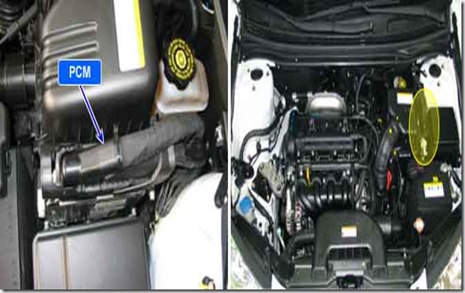
Auto Repair and Study Guide w/ Component Location

clip_image004

Study Guide and General Description

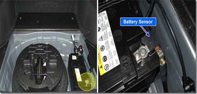
Many control units have applied to vehicle as it becomes more eletrolnical. These units control their own system based on information from diverse sensors. Therefore necessity of common use of diverse sensor information and importance of stable power supply are gathering strength. Battery sensor is mounted on battery (-) terminal. It transmits battery voltage, current, temperature information to ECM. ECM controls generating voltage by duty cycle based on these signals.

Auto Repair w/ DTC Description

ECM sets this code when there is an error in LIN communication line.

DTC Detecting Condition

Item

Detecting Condition

Possible cause

DTC Strategy

Signal Monitoring


=Open or short in LIN communication line

=UCU or ECM

EnableConditions

Engine Run Time  2sec.

Ignition Voltage  11V

Threshold value

LIN communication error

Diagnosis Time

Continuous

MIL On Condition

NO MIL ON(DTC only)

Diagnostic Circuit Diagram

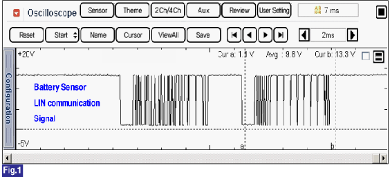
Signal Waveform & Data

clip_image005

More case and Repair Study

Sunday, September 26, 2010

How to Repair Engine Start But Suddenly Cut Off on idling Hyundai Sonata(YF)?

How to Repair Engine Start But Suddenly Cut Off on Idling Hyundai Sonata(YF)?

Model: Hyundai Sonata YF

Year Model: 2011

Fuel : Gasoline

Displacement: 2400cc

1) Study Guide For Condition

  1. Engine Start but Suddenly Cut Off on Idling.
  2. Engine Hesitate During Acceleration.

2) Auto Repair and Cause

  1. Due to the OCV clogging with metal.

3) Study Guide and Diagnosis

  1. Scan Tool Check = Trouble Code  P0011  Camshaft Position-Timing Over-Advanced or System Performance (Bank 1)
  2. Check if what are the possible causes of this problem.

    • Oil leak

    • Oil Control Valve

    • CVVT Assembly

  3. Perform Actuation test by GDS tools the OCV, its good activated
  4. Visually check
    =pull out the OCV
  5. The Problem is clogging with metal that’s why the timing will make over Advance.
  6. Repair The OCV pull out the Metal and returned
    = Finally Its Functioning normally.

More cases and Advice if you have some problem you can email me @ HERE 


Saturday, September 25, 2010

How to repair engine jerking during driving

How to repair engine jerking during driving.

Auto repair and Study guide Give’s you some Guidelines or tips that problem occurs from Hyundai cars hoping that this post help you.

Model: Hyundai Elantra(HD)

Year Model: 2010

Fuel :Gasoline

Displacement: 1600cc

1) Condition

  • Engine jerking during driving specially in high speed.
  • Engine suddenly loose power after jerking.

2) Study Guide

  • Due to the Ignition coil Extension wire.

3) Diagnosis

  • Scan tool check
    = No trouble code
  • Analyze the engine performance visually
  • Check for terminal wire loose
  • Ignition coil #1 socket terminal pin poor contact.

4) Auto Repair

  • Check and Repair terminal.

Engine Electrical System
 

ON-VEHICLE INSPECTION

SPARK TEST

1.Remove the engine cover(A).

2.Remove the engine cover bracket(A) and the ignition coil(B).

3.Remove the fuel pump relay(A) from the fuse box for fuel not to be injected while checking.

4.Using a spark plug socket, remove the spark plug.

5.Install the spark plug to the ignition coil. (1.6 CVVT)

6.Ground the spark plug to the engine.

7.Check if spark occurs while engine is being cranked.

Do not crank engine for more then 5~10 seonds.

8.Inspect all the spark plugs.

9.Using a spark plug socket, install the spark plug.

10.Install the ignition coil.


11.Install the engine cocer.


INSPECT SPARK PLUG

1.Study Guide Remove the engine cover bracket(A) and the ignition coil(B) with bolt.


When removing the ignition coil connector, pull the lock pin(A) and push the clip(B).

2.Using a spark plug socket, remove the spark plug.

Be careful that no contaminates enter through the spark plug holes.

3.Inspect the electrodes (A) and ceramic insulator (B).

AUTO REPAIR INSPECT IGNITION COIL

1.Measure the primary coil resistance between terminals (+) and (-).


More Tips and Case Study

Friday, September 24, 2010

How to Check Engine is Not Turned “OFF” in Hyundai Santa Fe

How to Check Engine is not turned “OFF” in Hyundai Santa Fe.


This Auto Repair and Study Guide give you some basic trouble of Engine and Electrical

Model: Santa Fe(SM)

Year Model": 2001

Displacement: 200cc

Fuel: Diesel

Study Guide : Engine is not turned “OFF”

1) Study Guide COndition

  1. When the ignition key is turned off the engine does not stop.
  2. Fuel consumption is High.

2) Auto Repair and Cause

  1. Scan tool check
    = No Trouble Code
  2. Inspect the injector using injector quantity comparison mode in GDS
    = Low injector quantity comparison value of #2 cylinder.
  3. Inspect after removing the injector.
    =The injector hole has been expanded.
    =After replacing the injectors, the engine system operates normally .
    =The deformed injector nuzzle may make the engine impossible to turn “OFF”

4) Auto Repair

  • Replace the injector assembly

More Info and reading

Thursday, September 23, 2010

How to repair the rear A/C not working of Hyundai Trajet

How to repair the rear a/c not working of Hyundai Trajet

Auto repair and Study guide for you to have tips if your Hyundai Trajet occurs problem from a/c system.

1) Condition

  • Rear Air condition system not working

2) Cause

  • This was occurs problem from engine compartment junction box A/C fuse burnt pin.

3) Diagnosis

  • Scan tool check
    = No trouble found
  • Seems were a Technician of Hyundai cars we will first check up visually Scan tool and Fuses.
  • Open and check for the fuse
    = Ok the fuse and the pin burn to the internal parts.

4) Auto Repair and Study guide

  • Replace passanger Fuse box assembly.


2006  G 2.0 DOHC  Relay Box (Engine Compartment)


FUSIBLE LINK

Study Guide SPECIFICATIONS

Circuit

Rated Capacity

Circuit

Rated Capacity

Ignition switch 1

30A

ABS 1

30A

Ignition switch 2

50A

ABS 2

30A

Power window

30A

Radiator

30A

Condenser

20A


Auto Repair and Study Guide INSPECTION

1.

Check for a burnt fusible link with an ohmmeter.

2.

If a fusible link burns out, there is a short or some other problem in the circuit. Carefully determine the cause and correct it before replacingthe fusible link.


Caution

The fusible link will burn out within 15 seconds if a higher than specified current flows through the circuit.

Study Guide and Study Guide

Trouble and Study

Tuesday, September 21, 2010

How to check Code C1202 Wheel Speed Sensor Front-LH Invalid/no Signal

How to check code c1202 wheel speed sensor front LH invalid/no signal

This Auto repair and Study guide was trouble encounter from Hyundai Genesis regarding on ECS/ABS light indicator on some times while driving. this was the trouble code appeared from the GDS C1202 Wheel speed sensor but some of trouble can not immediately caught base on the trouble code given by the GDS this is only the basis so that every technician has pattern.

Auto repair and Study guide This trouble was solve and the cause was only from the tire. all tire defective oblong that’s why the sensor from wheel can not give good signal.

Component Location,Auto repair and Study guide


Study guide General Description

Study guide The ESP system is the shorten word of Electronic Stability Program system. This system recognizes a critical driving condition by Yaw-rate sensor, Lateral acceleration sensor and Steering angle sensor. And then it stabilizes the Study guide and vehicle by a individual wheel braking and engine torque control through CAN communication. Among components of this system, the wheel speed sensor(WSS) is the essential component of the brake system. Study guide The ESP ECU(HECU, Hydraulic and Electronic Control Unit) uses the wheel speed sensor's signals to calculate a vehicle speed and also this Auto repair to determine whether a wheel lock occurs or not.

Auto repair DTC Description

Study guide of The HECU monitors the wheel speed sensor signal continuously and if the signal of a wheel speed sensor is omitted or too low, this DTC is set.

DTC Detecting Condition and Auto repair.

Item
Detecting Condition
Possible Cause

• Signal Monitoring

• Poor connection

• Improper installation of wheel speed sensor

• Abnormal Rotor and wheel bearing

• Faulty Wheel speed sensor

Threshold valve

• Vehicle speed = 10 kph(6.2 mph)

-Study guide and Auto repair when the maximum wheel speed is continuously over 10 km/h(6.2mph) and the other wheel speed is below 2 km/h(1.2 mph) for more than 180 seconds

• Vehicle speed = 15 kph (9.3 mph)

1. when the maximum wheel speed is continuously over 15km/h(9.3 mph) and the minimum wheel speed is below (0.4× the maximum wheel speed) for more than 120 seconds

2. when the maximum wheel speed is continuously over 40km/h(24.8 mph) and the minimum wheel speed is below (0.6× the maximum wheel speed) for more than 120 seconds

• when the brake pressure goes down or keeps up for more than 28 seconds as Study guide.

Fail-Safe

1.Only one wheel failure

: The ABS/TCS/ESP functions are inhibited.

The ABS/ESP warning lamps are activated, the EBD warning lamp is not activated.

2.More than two wheels failure

: The ABS/EBD/TCS/ESP functions are inhibited.

The ABS/EBD/ESP warning lamps are activated.

MORE INFORMATION AND TROUBLE SHOOTING


Study guide  and  Auto repair / Study guide and Auto repair / Study guide and Auto repair

Monday, September 20, 2010

How to Check ESP Code C1101 Battery Voltage High

How to Check ESP Code C1101 Battery Voltage High

 Electronic Stability Program C1101 Battery Voltage High

 Auto repair

Study guide

Study guide Component Location

clip_image004

Auto repair and Study guide w/ General Description

Study guide for the ESP system is the shorten word of Electronic Stability Program system. Study guide This system recognizes a critical driving condition by Yaw-rate sensor, Lateral acceleration sensor and Steering angle sensor. And then it stabilizes the vehicle by a individual wheel braking and engine torque control through CAN communication. Study guide The ESP ECU(HECU, Hydraulic and Electronic Control Unit) checks the battery voltage and alternator output voltage to determine, as a safety issue, whether this system can operate normally or not.Study guide The normal battery voltage range is essential for controlling this system as intended.


Study guide DTC Description

The HECU monitors the voltage of battery and if it stays more than 17 Volts, this DTC is set.

DTC Detecting Condition

Item and Study guide

Auto repair w/ Detecting Condition

Possible Cause or Study guide

DTC Strategy and Study guide

Monitoring the voltage of battery

Poor connection in power supply circuit

Faulty Alterator

Faulty HECU

Threshold valve and Study guide

When Battery voltage is more than 17V

Fail-Safe and Study guide

ABS/EBD/TCS/ESP funtions are inhibited.

ABS/EBD/ESP warning lamps are activated.

Study guide and Specifications

Normal Voltage Range

IGN "ON" or Engine "ON"

10V ~ 16V

more guide and Study

Auto repair , Study guide , Auto repair , Study guide , Auto repair , Study guide , Auto repair

Sunday, September 19, 2010

How to Chect Code P0880 TCM Power Signal Error Open/Short (GND)

How to Check Code P0880 TCM Power Signal Error Open/Short (GRD)

Component Location


Auto repair and Study guide General Description

The HIVEC Automatic Transmission supplies the power to the solenoid valves by way of a control relay. When the TCM sets the relay to ON, the relay operates and the battery power is supplied to all the solenoid valves. When the TCM sets the relay to OFF, all solenoid valve power is shut off and the transmission is held in the 3rd gear position. (Fail Safe Mode ) 

Auto repair and Study guide DTC Description

Study guide The TCM checks the A/T control relay signal by monitoring the contol signal. If, after the iginiton key is turned on, an unexpected voltage value, which is quite a bit lower than battery voltage is detected, the TCM sets this code. 

DTC Detecting Condition

Auto repair and Study guide
Detecting Condition
Possible Cause 

• Check voltage range

• Open or short in circuit

• Faulty A/T control relay

• Faulty PCM/TCM

Enable Conditions Study guide

• 22V  Voltage Battery 9V

• Time after TCM turns on 0.5sec

Threshold Value

• Voltage 7V or Voltage  24.5V 

How to check Code P0880 TCM Power Signal Error Open/Short (GND)

Auto repair and Study guide Monitor Scantool Data

1. Connect scantool to data link connector(DLC)

2. Ignition "ON" & Engine "OFF".

3. Monitor the "A/T CON. RELAY VOLT" parameter on the scantool


Specification: Approx. B+


4. Is A/T RELAY VOLT within specifications?

▶ Fault is intermittent caused by poor contact in the sensor's and/or TCM(PCM)'s connector or was repaired and TCM(PCM) memory was not cleared.Study guide Throughly check connectors for looseness, poor connection, bending, corrosion, contamination, deterioration or damage.Repair or replace as necessary and go to Auto repair "Verification Vehicle Repair" procedure.

▶ Go to "W/Harness Inspection" procedure.


How to check Code P0880 TCM Power Signal Error Open/Short (GND)
 

Auto repair and Study guide Terminal and Connector Inspection

1. Many malfunctions in the electrical system are caused by poor harness and terminals. Faults can also be caused by interference from other electrical systems, and mechanical or chemical damage.

2. Thoroughly check connectors for looseness, poor connection, bending, corrosion, contamination, deterioration, or damage.

3. Has a problem been found?

▶ Repair as necessary and go to Auto repair "Verification vehicle Repair" procedure

▶ Go to Auto repair "Power Circuit Inspection" procedure

Study guide Power Circuit Inspection

1. Ignition "ON" & Engine "OFF".

2. Disconnect the "A/T CONTROL RELAY" connector

3. Measure the voltage between terminal "1" of the "A/T CONTROL RELAY" harness connector and chassis ground.


Specification: Approx. B+


4. Is voltage within specifications?

▶ Go to Auto repair "Signal Circuit Inspection" procedure

▶ Check that A/T-20A Fuse in engine room junction is installed or not blown.
▶ Check for open in harness. Repair as necessary and Go to "Verification Vehicle Repair" procedure and Study guide.

Auto repair and Study guide Signal Circuit Inspection

Check A/T Control Relay Harness

1. Ignition "OFF".

2. Disconnect the "A/T CONTROL RELAY" connector

3. Measure the voltage between terminal "4" of the "A/T CONTROL RELAY" harness connector and chassis ground.

4. Turn ignition switch OFF → ON


Specification: 12V is measured only for approx. 0.5sec


5. Is resistance within specifications?

▶ Go to "Check Supplying Power to solenoid valve" procedure

▶ Check for open in harness. Repair as necessary and Go to "Verification Vehicle Repair" procedure
▶ If signal circuit is OK,Substitute with a known-good PCM/TCM and check for proper operation. If the problem is corrected, replace PCM/TCM and then go to "Verification of Vehicle Repair" procedure.

Check Supplying Power to Solenoid Valve Harness

1. Ignition "OFF"".

2. Disconnect the "A/T CONTROL RELAY" and PCM/TCM connector

3. Measure the resistance between terminal "3" of the "A/T CONTROL RELAY" harness connector and terminal "49, 50" of the PCM/TCM harness connector


Specification: Approx. 0 Ω


4. Is resistance within specifications?

▶ Go to "Ground Circuit Inspection" procedure

▶ Check that A/T-20A Fuse in engine room junction is installed or not blown.
▶ Check for open in harness. Repair as necessary and Go to "Verification Vehicle Repair" procedure

Auto repair And Study guide Ground Circuit Inspection

1. Ignition "OFF".

2. Connect the "A/T CONTROL RELAY" connector

3. Measure the resistance between terminal "2" of the "A/T CONTROL RELAY" harness connector and chassis ground


Specification : Approx. 0 Ω


4. Is resistance within specifications?

▶ Go to "Component Inspection" procedure

▶ Check for open in harness. Repair as necessary and Go to "Verification Vehicle Repair" procedure

more case study and please try to leave comment


Auto repair , Study guide , Auto repair , Study guide , Auto repair , Study guide