How to Repair Electronic Steering
This can aply to all brand of Automobile that consist of EPS (Electronic Power Steering)
| | Hyundai I30 Steering System | | |
| AUTO REPAIR AND STUDY GUIDE AND DESCRIPTION | Study Guide of EPS (Electric power steering, Column assist type) system uses an electric motor to assist the steering force and it is an engine operation independent steering system. Study Guide of EPS control module controls the motor operation according to information received from the each sensor and CAN (Controller Area Network), resulting in a more precise and timely control of steering assist than conventional engine-driven hydraulic systems. Components (Steering Angle Sensor, Torque Sensor, Fail-safe relay, etc.) of the EPS system are located inside the steering column & EPS unit assembly and the steering column & EPS unit assembly must not be disassemble to inspect or replace them. NOTES WITH REGARD TO DIAGNOSIS | Trouble factor | Check item | Trouble symtom | Explanation | Note | | Drop, impact, and overload | Motor | Abnormal noise | | - | Visable or unvisable damage can occur. The steering wheel could pull to one side by using the dropped parts. | | - | Precise parts of motor/ECU are sensitive to vibration and impact. | | - | Overload can cause unexpected damage | | | - | Do not use the impacted EPS. | | - | Do not overload each parts. | | | ECU | Circuit damage | | Torque sensor | Insufficient steering effort | Overload to INPUT shaft can cause malfunction of the torque sensor | | - | Do not impact the connecting parts (When inserting and torquing) | | - | Use the specified tool to remove the steering wheel. (Do not hammer on it) | | - | Do not use the impacted EPS | | | Shaft | Insufficient steering effort (Uneven between LH and RH) | | Do not use the impacted EPS | | Pull/Dent | Harness | | - | Malfunction-impossible power operation | | Disconnection between harness connecting portion and harness | Do not overload the harness | | Abnormal storage temperature | Motor/ECU | Abnormal steering effort by improper operation of the motor/ECU | | - | Waterproof at the normal condition | | - | Even a little moisture can cause malfunction of the precise parts of the motor/ECU | | | - | Keep the normal temperature and proper moisture, while storaging | | | 1. | Do not impact the electronic parts, if they are dropped or impacted, replace them with new ones. | | 2. | Avoid heat and moisture to the electronic parts. | | 3. | Do not contact the connect terminal to avoid deformation and static electricity. | | 4. | Do not impact the motor and torque sensor parts, if they are dropped or impacted, replace them with new ones. | | 5. | The connector should be disconnected or connected with IG OFF. | |
| 
|
Auto Repair and Study Guide , Auto Repair and Study Guide
After or before servicing the EPS system, perform the troubleshooting and test procedure as follows. Compare the system condition with normal condition in the table below and if abnormal symptom is detected, perform necessary remedy and inspection. | Test condition | Normal condition: Motor must not supply steering assist. | | Symptom | Possible cause | Remedy | | IG Off | Motor supplies steering assist. | ASP is not calibrated. | Perform the ASP calibration using a scan tool. | | IG power supplies | Inspect the IG power supply line. | | Test condition | Normal condition: Motor must not supply steering assist, Warning lamp is illuminated. | | Symptom | Possible cause | Remedy | | IG On/Engine Off | Motor supplies steering assist. | ASP is not calibrated. | Perform the ASP calibration using a scan tool. | | EMS CAN signal is not received. | Inspect the CAN line. | | Warning lamp is not illuminated. | Cluster fault | Inspect the cluster and cluster harness | | Test condition | Normal condition: Motor supplies steering assist, Warning lamp is not illuminated. | | Symptom | Possible cause | Remedy | | IG On/Engine On | Warning lamp is illuminated and Motor dose not supply steering assist. | EPS (Hot at all times) and IG power supply fault | Inspect the connector and harness for EPS (Hot at all times) and IG power supply line. | | DTC is detected by system. | Perform the self test using a scan tool and repair or replace. | | Warning lamp is illuminated and Motor supplies steering assist. | ASP is not calibrated. | Perform the ASP calibration using a scan tool. | | CAN communication between EPS and cluster is fault. | Inspect the CAN line. | ASP: Absolute Steering Position CAN: Controller Area Network EMS: Engine Management System | 
| | Auto Repair and Study Guide | The following symptoms may be occurred during normal vehicle operation and if there is no EPS warning light illumination, it is not malfunction of EPS system. | • | After turning the ignition switch on, the steering wheel becomes heavier while it performs EPS system diagnostics, for about 2 seconds, then it becomes normal steering condition. | | • | After turning the ignition switch on or off, EPS relay noise may occur but it is normal. | | • | When it is steered, while the vehicle is stopped or in low driving speed, motor noise may occur but it is normal operating one. | | Caution when ASP (Absolute Steering Position) calibration or EPS type recognition | • | Check if the battery is fully charged before ASP calibration or EPS type recognition. | | • | Be careful not to disconnect any cables connected to the vehicle or scan tool during ASP calibration or EPS type recognition. | | • | When the ASP calibration or EPS type recognition is completed, turn the ignition switch off and wait for several seconds, then start the engine to confirm normal operation of the vehicle. | Scan tool (Hi-Scan Pro) installation | 1. | Attach the CAN interface module to the Hi-Scan Pro main body and securely tighten the two bolts. | | 2. | Install the CAN interface module to the Data Link Cable and securely tighten the two bolts. | ASP calibration procedure | 1. | Plug DLC cable from a scan tool into the vehicle's data link connector located under the instrument panel on the driver's side. | | 2. | Turn the ignition switch ON position. | | 3. | Turn the steering wheel so that the front wheel can face straight ahead. | | 4. | Select a model and ELECTRIC POWER STEERING. 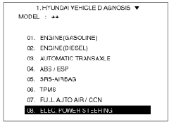
| | 5. | Select the ASP CALIBRATION and press ENTER. 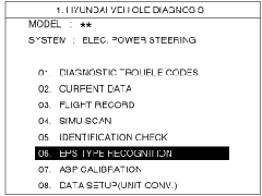
| | 6. | Check the massage on the screen and press ENTER'. 
| | 7. | Confirm the vehicle condition (IG On) and then turn the steering wheel until massage changes to the next screen. 
| | 8. | When the massage is displayed on the screen as follows, turn the steering wheel so that the front wheel can face straight ahead and then press ENTER. 
| | 9. | When the calibration is completed, the massage will be displayed on the screen as follows. 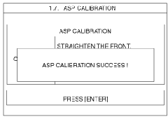
| EPS type recognition procedure | 1. | Plug DLC cable from a scan tool into the vehicle's data link connector located under the instrument panel on the driver's side. | | 2. | Turn the ignition switch ON position. | | 3. | Select a model and ELECTRIC POWER STEERING. ![clip_image005[1]](https://blogger.googleusercontent.com/img/b/R29vZ2xl/AVvXsEgY3JHHtNE8c42w7-_dTj8JQzwpTCs_54etvMAX16pOUuDXismABZ6pKnp6O0WWTmtlBp2tBfAlOKbtL-0mEv88cAhTaraNc_OCDNPYwWuUPbsXtwasHNmisuhDCmgGUvAx86IPvE7EpMYz/?imgmax=800 "clip_image005[1]")
| | 4. | Select the EPS type recognition and press ENTER. 
| | 5. | Select the affected area and press ENTER. 
| | 6. | When the EPS type recognition is completed, the massage will be displayed on the screen as follows. 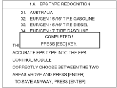
| |
more information and Study Guide


![clip_image005[1]](https://blogger.googleusercontent.com/img/b/R29vZ2xl/AVvXsEhY70q_Z6nRx5Ey0MkQ-KDjddGZNAoTy2ZwT4U3hp1WKCEwuJZL_7S6-5FMeYIJU3hn9Qp-tJZfrvA-Htf6REjtNCvFkowz-LoBrPYiRAaGheGopEpg1jsKKg1xRtCA4NoOZcNylqRGS0EC/s1600-h/clip_image005%5B1%5D%5B2%5D.gif "clip_image005[1]")


